Development of Intelligent Robotic Workstations Industrial Project in collaboration with B & R Automation
2023-2024
Miao.Lu Jiaxiu.Xu
Xiang.Zhou Yifan.Huang

Project Background
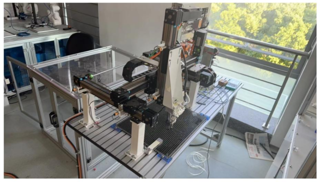
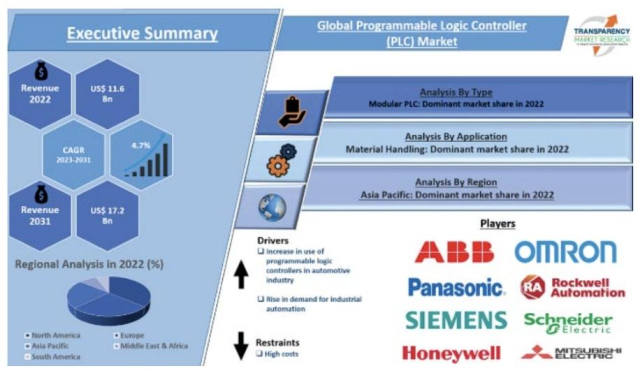
Analysis of Existing Products: Gantry robots are widely used in industrial production. They can improve efficiency and reduce costs, and PLC products from different brands have their respective advantages. Meanwhile, the automation design software Automation Studio is widely used in control system design, with functions such as multi-disciplinary design and simulation analysis. However, existing gantry frames have issues like insufficient grasping ability and low grasping accuracy. For example, the Z – axis lacks real – time feedback, and the lack of closed – loop control for the X and Y axes leads to cumulative errors.
Figure 1: Gantry structure Figure 2: PLC Market
Customer Needs and Design Requirements: Customers expect the robot to be able to grasp fixed objects at random positions and improve the grasping success rate. The design requirements include using a 2D camera as the vision system for precise positioning, and applying PID control and pressure sensors to enhance grasping ability and prevent motion errors.
Project Planning and Workload Distribution: The project aims to provide an automated grasping solution for the gantry structure. Team members have clear divisions of labor, each responsible for different parts of the system, report writing, and result presentation.
Comparison, Development, and Screening of Design Concepts
Comparison of Manipulators: Serial, parallel, and gantry manipulators have different characteristics in structure, application, and performance. Serial manipulators are highly adaptable but have weak stability and load – bearing capacity. Parallel manipulators have high precision and large load – bearing capacity but a small workspace. Gantry manipulators are suitable for large – scale material handling, with excellent stability and load – bearing capacity, but inferior flexibility and precision.
Comparison of Design Concepts of Different Companies: Rockwell focuses on ease of use, safety, environmental protection, and energy conservation, integrating technical experience with market demands. Fanuc emphasizes the rigidity, stability, high precision, and scalability of the gantry, and uses advanced technologies to enhance the automation level. B&R has advantages in highly integrated automation solutions, strong motion control capabilities, and support for smart manufacturing in gantry systems.
Vision System: Fixed vision systems are simple and cost – effective but have limited visibility and accuracy in dynamic environments. Mobile vision systems are more complex and costly but can ensure continuous and clear vision, performing better in precise object detection and positioning.
Pressure Sensing: Traditional fixed – pressure sensing has poor flexibility and is prone to errors due to changes in the height and position of the target. Dynamic feedback pressure sensing can provide real – time feedback, enhancing the system’s adaptability and grasping reliability and reducing the risk of damaging fragile targets.
Development and Screening Process: First, prototypes of fixed and mobile vision systems were made and tested to determine the advantages of mobile vision systems, and different PLC and pressure sensor configurations were also tested. Subsequently, the PLC control algorithm (especially PID control) and the vision system algorithm were optimized. Finally, B&R PLC, mobile vision systems, and dynamic pressure sensors were integrated and comprehensively tested in simulated and real – world environments.
Prototyping and Testing
Prototyping
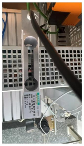
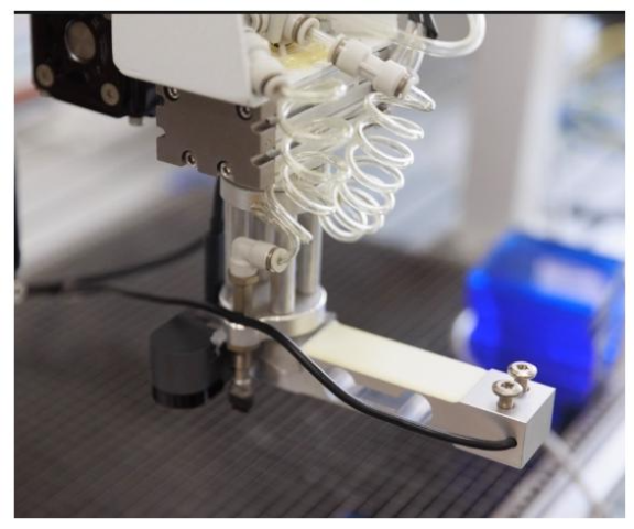
Pressure Sensor: To solve the problem of the air pump turning on prematurely or late when the existing machine sucks the target object, the HYPX – 017 pressure sensor and the supporting HY – XSA single – channel digital weight transmitter were installed on the same plane as the air pump port. They communicate with Automation Studio through the RS232 interface and the Modbus communication protocol.
Figure 3: HYPX-017 Pressure sensor Figure 4: Installation pressure transducer
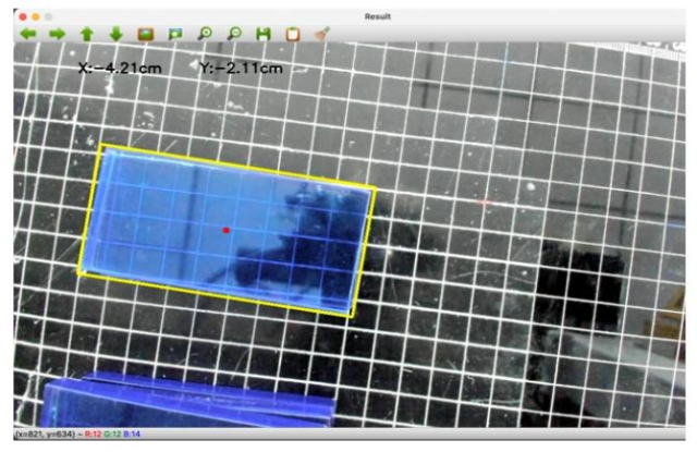
Camera: A 2D camera was selected because of its rich algorithms, low cost, and fast recognition speed. Python and the OpenCV framework were used for image recognition. The geometric center pixel coordinates of the target object were obtained through image algorithms and converted into actual coordinates. To address the issues of blocked camera vision and the impact of Z – axis movement on measurement, the camera was installed on the robotic claw, and the grid on the gantry’s operating table was used to calculate the physical distance per pixel. The deviation between the camera’s optical axis and the landing point of the robotic claw was also compensated.
Figure 5: Position Identification Screen
Control Design: First, the previous code was reproduced to make the machine move normally, during which many parameter – setting and origin – setting problems were solved. Then, the motion accuracy was optimized by adjusting the proportional (P), integral (I), and derivative (D) parameters of PID control.
Testing
Vision Testing: Blue square objects were placed at different positions for testing. The recognition accuracy was high, with a maximum error of less than 2.5mm and an average error of less than 1.2mm. The measurement error was smaller when the object was closer to the edge of the screen. However, the camera has image distortion, and high – resolution images increase the processing pressure on the computer, resulting in a low detection frame rate. Currently, it only supports the recognition of simple – shaped objects.
Control Testing: The motion performance of the three – axis gantry was tested in a standard environment, including position accuracy, repeat positioning accuracy, parallelism and perpendicularity, speed and acceleration, and load testing. The test results show that the position and repeat positioning accuracy of the three axes are within the allowable error range, but the Z – axis position error is relatively large. The speed and acceleration errors of each axis are within ±5%. After the load test, the accuracy of each axis decreased slightly but still met the standard. It is recommended to optimize the Z – axis accuracy, adjust the parallelism and perpendicularity between the axes, and conduct regular maintenance and calibration.
Project Conclusions
Summary of the Design Process: The design process covers aspects such as requirement understanding, selection of hardware and software, programming, testing, and application implementation. In the future, it is necessary to continuously maintain the PLC system, monitor and repair the system, train operators, and keep up with technological development, considering the scalability and adaptability of the system.
Project Achievements: The project uses B&R automation equipment and integrates modern sensors, PID control, and vision systems to improve the grasping and handling performance of industrial robots. The test results show that the motion performance of the three – axis gantry generally meets the design standards, but there is still room for improvement in Z – axis accuracy and the parallelism and perpendicularity between the axes.
Social Responsibilities: B&R PLC undertakes multiple responsibilities in promoting equality, diversity, and inclusion, such as treating employees equally, building a diverse workforce, and creating an inclusive working environment. This can bring many benefits, such as promoting innovation, expanding the talent pool, and improving employee satisfaction. It also has important significance, including reflecting fairness, enhancing corporate competitiveness, and fulfilling social responsibilities.
Environmental and Social Impacts: B&R PLC can improve the automation level of industrial production, reduce the consumption of raw materials and energy, and reduce environmental impacts. It can also create technical jobs and promote economic growth, but it may also lead to job losses in some industries and exacerbate the digital divide and inequality.
